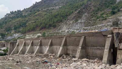
A retaining wall is a rigid structure build to retain the soil or the masses of debris at one end having different levels so that the soil masses don’t slip from it.
Thus, retaining walls are specially designed for lateral earth pressure and forces. The retaining wall further protects the direct vertical exposure of soil at different elevation and thus reduced the erosion and maintain slope stability.
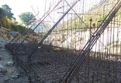
Counterfort retaining wall is those retaining wall which withstands all the lateral forces by its flexural action rather than its weight. So such wall has a broad base foundation, vertical stem reinforced with bar and supported by thin transverse slabs called Counterfort placed at regular intervals.
The slab is specially designed to place inside the section where the soil mass has to be retained and thus is designed for high tensional stress. But if the slab is kept outside, where the soil mass has not to be retained, then they are called Buttress and know as Buttress retaining wall.
And if the wall doesn’t contain any Counterfort or Buttress then they are simply known as cantilever retaining wall. A cantilever wall with a larger stem requires a huge base, so in order to remove this limitation, Counterfort walls are designed with transverse support.
Parts of Counterfort retaining wall
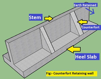
1) Stem: It is the thin and vertical erectile part of the counterfort wall which retains the soil or backfilling.
The stem of the counterfort wall can be analog to the two-way slab with three fixed ends as well as a free end, which transfers its load at the base of the stem in form of bending moments and then transfers to the base slab.
2) Base slab: The base slab is the footing of the counterfort wall which supports the stem and counterforts.
The base slab gathers all the load and moments from the upper structure and transfers it safely to the ground.it further is divided into two parts.
3) Toe slab: The base slab outside the retaining section is called the toe slab. This part doesn’t contain the transverse supporting slabs.
4) Heel slab: The base slab that lies inside the retaining section of the wall is called the heel slab. This part contains the transverse supporting slender slab called counterforts.
5) Counterforts: They are thin transverse slabs connected at the heel of the base slab to support the stem, placed at definite spacing.
6) Drainage System:- It is an integral part of the counterfort retaining wall whose function is to control the internal water pressure which consists of weep holes and drain.
7) Facing:- Facing is the outermost or exterior part of the retaining wall which is constructed with different materials for aesthetic purposes or to prevent outer environment contact.
8) Anchorage System:- Anchorage is the extra anchors or tiebacks which are used to provide extra stability to the counterfort retaining wall.
9) Foundation:- Foundation is the most important part of the wall which take all loads from the backfill and transfer them vertically to the soil.
The counterforts lie inside the backfilling part of the wall. They can be up to the full height of the wall as well as up to the partial (slightly greater than half) height of the wall stem. Counterforts help to reduce the bending moment at the wall stem.
Types of Counterfort retaining wall
On the basis of material
- Reinforced cement concrete
- Masonry Counterfort wall
- Timber and wood Counterfort
- Steel structures Counterfort
On the basis of transverse support
- Full height Counterfort
- Partial height Counterfort
- Counterfort along with Buttress
Design of counterfort retaining Walls
The design of any retaining walls depends upon a number of parameters and factors such as soil parameters: liquidity limit, water content, the density of soil, cohesiveness property of soil, bearing capacity, angle of friction to the wall, angle of shearing resistance in soil; the difference in elevation; the presence of water table, etc.
Before design of wall the soil property at site must be studied properly and the values of parameters are needed to be found out. Then the following procedures may be continued for design of counterfort wall.
1) Determine the Dimension using General proportion
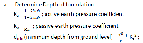
q0 is safe bearing capacity, γ is unit weight of soil
Select the appropriate depth df greater than dmin
b. Determine the total height of wall (H)
H = df + height above the ground level required
c) Determine Base slab width
Base slab width (b) = 0.6 H – 0.7H
d) Determine toe width (btoe)
Maximum btoe = b/3
Minimum btoe = 0.1H
Select appropriate value for btoe between maximum and minimum ranges.
e) Determine the thickness of slab
Equivalent height of earth as surcharge, hs = ws/γ ; ws is surcharge pressure
Thickness of base slab = 0.08 (H+hs) ; if surcharge pressure is available
Thickness of base slab = H/20 to H/15 ; if surcharge pressure is not available
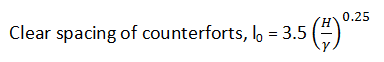
f) Determine the dimension and spacing of counterforts
Thickness of counterfort must be greater than 0.3. Assume suitable value.
Thickness of stem = 0.1m – 0.2m
Effective span ,l = Minimum of (c/c between counterfort , l0 + thickness of stem)
g) Determine Thickness of stem near the base (bstem),
Depth of wall upto base of stem; hbase = H – thickness of slab
Pressure exerted at bottom , w= Ka * γ * hbase
For bending moment condition
Note: Maximum bending moment occurs at support. And the stem is considered as a slab supported by counterfort as support.

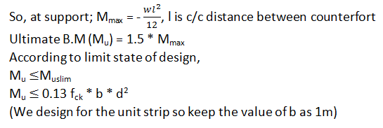
Determine minimum value of d from there.
For shear condition,
Considering for shear the value of d must be taken 1.5 times to 3 times obtain from the bending moment condition.
Take d = * d obtain from BM condition
Assume cover,C
Total thickness at base of stem (bstem) = d+C
Note : If the design is only done considering dimensional proportional then, sometimes the base of stem is directly taken as 0.1H to neglect the cumbersome of reinforcement design approach.
h) Determine heel width (bheel)
bheel = b – btoe –bstem
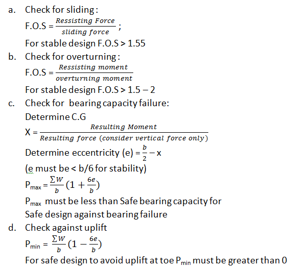
2) Check for stability
Determine the required lateral forces, bearing pressure , resultant forces, resultant moments, resisting force, frictional force,sliding force , resisting moments ,overturmimg moments using appropriate formula and techniques.
If any of above check gives the result failure then the design must be repeated with greater assumption values in order to create safe design.
3) RCC design of the counterfort wall.
After the design of required dimension, the wall is now subjected to design for reinforcement bars with help of the design for Rcc slab ,Rcc beam and Rcc footing. Or it can be directly design through modern structural designing apps.
Note: The stem of the wall acts as, two way slab in the middle panel between two counterforts with three end fixed and acts as two way slab with free end at the ends, so it can be design analogously as two way slab.
The base or footing is also design as similar to the Rcc slab and Rcc footing. The toe slab however can be treated as cantilever beam if buttress are not provided.
The counterforts are designed as analogy to vertical tappering cantilever with base being fixed. They are assumed as T beams (due to direct interference of the stem of wall) with depth of section varying from free edge to fixed edge.
I hope this article on “Counterfort retaining wall” remains helpful for you.
Happy Learning – Civil Concept
Contributed by,
Civil Engineer – Rajan Shrestha
Read Also,
Methods of plastering on wall or Civil Engineering Structure
How to build a curved brick wall? Step by Step Procedure
How to calculate bricks in a wall pdf – With Brick Masonry Pier
What is shear wall Why and Where it is provided – Best Location